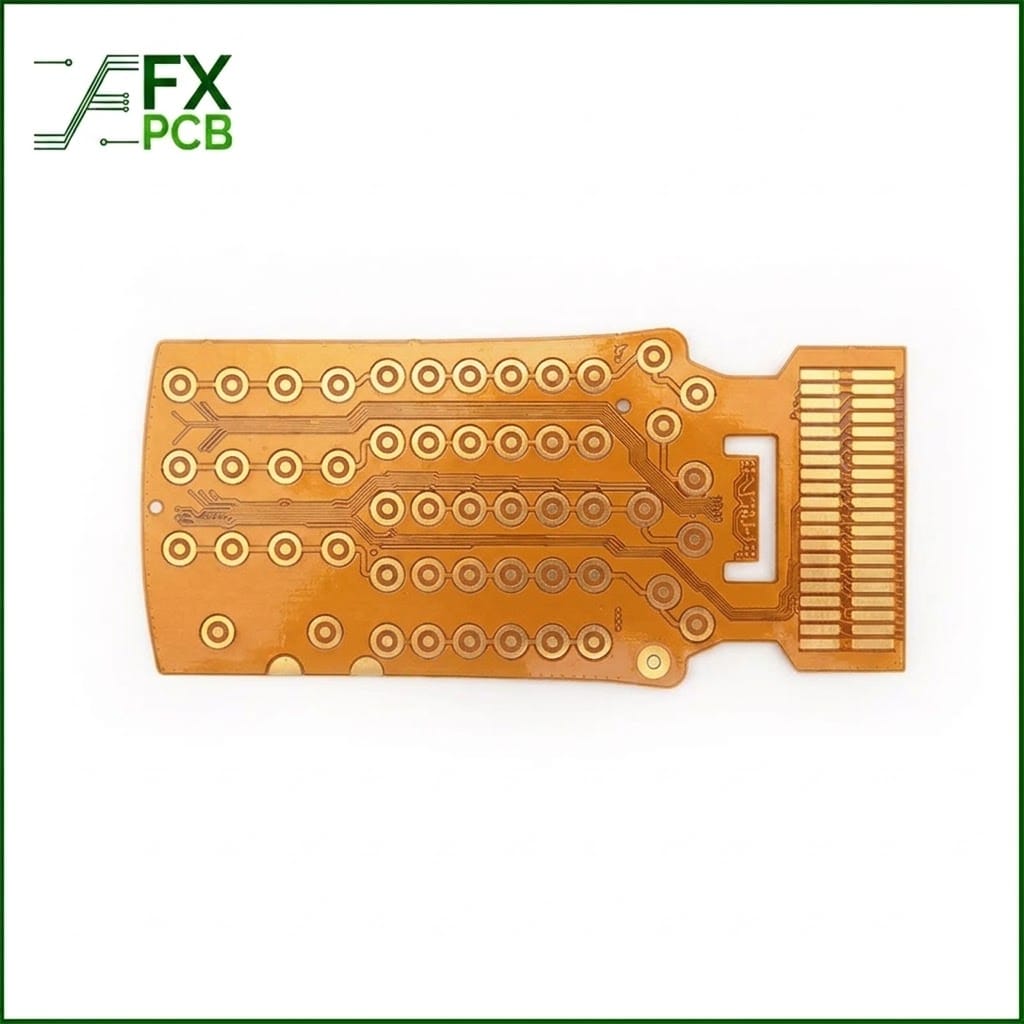
Description
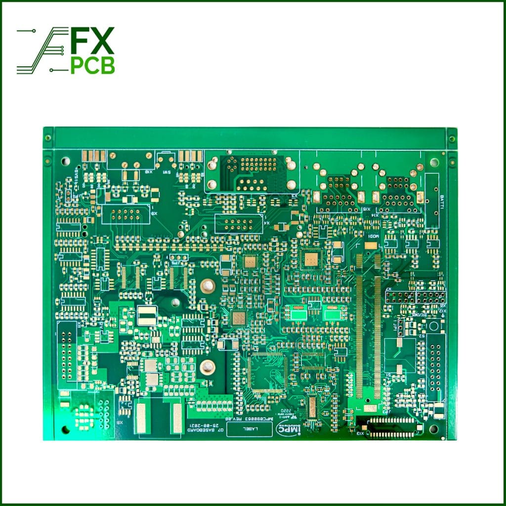
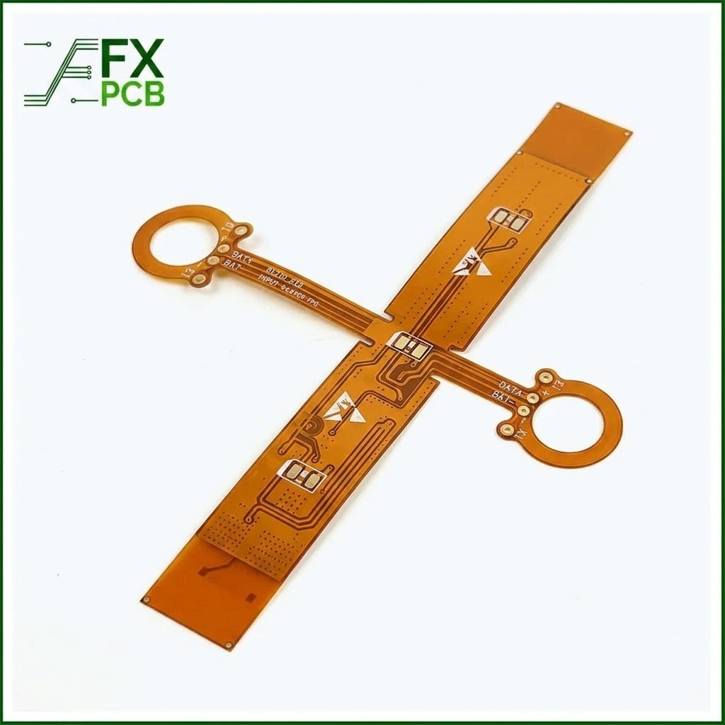
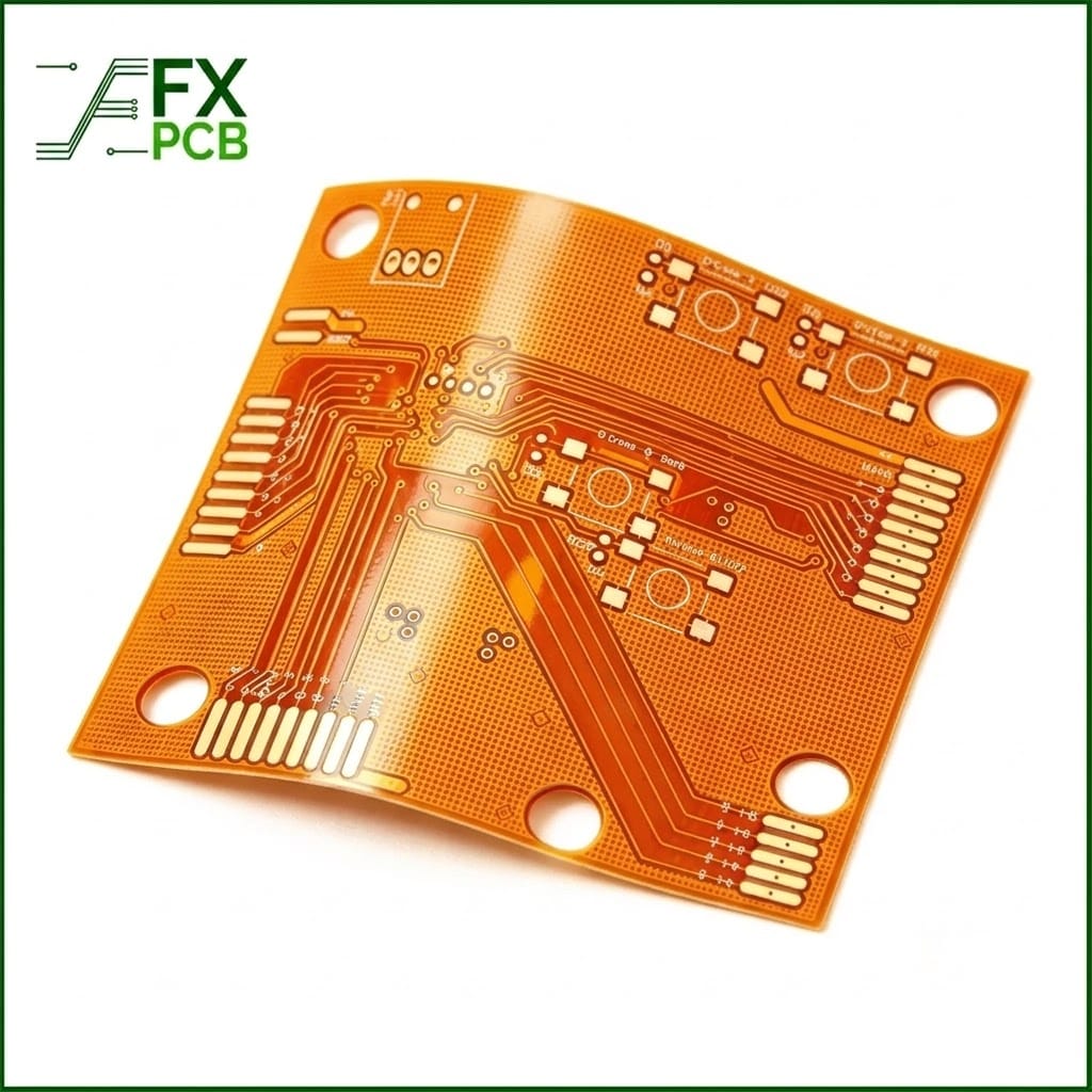
Get your flexible and rigid-flex PCB designs manufactured fast and accurately. We build 1 to 24-layer flex boards in-house with ready-to-use Polyimide (PI) and Polyester(PET) material in stock,and free DFM verification and stack up before production starts.
Turnaround: 24–48 Hours Expedited Available
Layer Count: 1–24 Layers (FPC) / Up to 20 Layers (Rigid-Flex)
Quality Assurance: IPC-6013,ISO9001, UL
Pre-Production Support: 100% Free CAM & DFM Review on Every Order

Guaranteed Turnaround Times (Lead Time Matrix)
We maintain standing inventories of premium Polyimide (PI) substrates, coverlays, and stiffeners to ensure uninterrupted, rapid manufacturing.
| Product Type | Layer Count | Standard Prototype Lead Time | Expedited Quick Turn Lead Time |
| Single / Double-Sided FPC | 1–2 Layers | 3–4 Working Days | 24–48 Hours |
| Multilayer Flexible PCB | 3–6 Layers | 5–7 Working Days | 3–4 Working Days |
| Rigid-Flex PCB | 2–8 Layers | 7–9 Working Days | 4–5 Working Days |
Technical Specifications & Manufacturing Capabilities
Our cutting-edge laser drilling, roll-to-roll (R2R) processing, and vacuum lamination systems support both fine-pitch rapid prototyping and volume production.
| Parameter | Standard Production Capability | Advanced / Prototype Capability |
| Supported Board Types | Single/Double-Sided, Air-Gap / Sculptured, Multilayer, Rigid-Flex | Single/Double-Sided, Air-Gap / Sculptured, Multilayer, Rigid-Flex |
| Layer Count | 1–20 Layers (FPC) / 2–16 Layers (Rigid-Flex) | 1–24 Layers (FPC) / 2–20 Layers (Rigid-Flex) |
| Max Board Dimensions | FPC: Roll-to-Roll (R2R); Rigid-Flex: 250 × 1500 mm | FPC: Roll-to-Roll (R2R); Rigid-Flex: 250 × 1700 mm |
| Finished Thickness Range | FPC: 0.06–0.5 mm; Rigid-Flex: 0.25–6.0 mm | FPC: 0.06–0.5 mm; Rigid-Flex: 0.25–6.0 mm |
| HDI Blind & Buried Vias | 1–2 Step HDI | 1–4 Step HDI |
| Min. Trace Width / Spacing | 0.04 / 0.04 mm (approx. 1.6 / 1.6 mil) | 0.035 / 0.035 mm (approx. 1.4 / 1.4 mil) |
| Base Raw Materials | Polyimide (PI), PET, Electro-Deposited (ED) Copper, Rolled-Annealed (RA) Copper | Polyimide (PI), PET, Electro-Deposited (ED) Copper, Rolled-Annealed (RA) Copper |
| Copper Foil Thickness | 9, 12, 18, 36, 70, 105, 140, 175 µm | 6, 9, 12, 18, 36, 70, 105, 140, 175, 210 µm |
| Dielectric / Insulation Layer | 12.5, 25, 50, 70, 100, 125 µm | 12.5, 25, 50, 70, 100, 125, 150, 175 µm |
| Min. Mechanical Drill Hole | 0.1 mm (CNC Drill) | 0.1 mm (CNC Drill) |
| Min. Laser Microvia | 0.075 mm (Laser Drill) | 0.05 mm (Laser Drill) |
| Hole Diameter Tolerance | +/- 0.05mm | +/-0.05mm |
| Stiffener Types | FR4, Polyimide (PI), PET, Stainless Steel (SUS), PSA Tape (3M series) | FR4, Polyimide (PI), PET, Stainless Steel (SUS), PSA Tape (3M series) |
| Surface Finishes | ENIG (Immersion Gold), ENEPIG, Immersion Silver, Immersion Tin, Hard Gold Plating, OSP | ENIG (Immersion Gold), ENEPIG, Immersion Silver, Immersion Tin, Hard Gold Plating, OSP |
| Impedance Control | 50–120Ω±10% | 50–120Ω±10% |
Why Choose Us for Rapid Flex PCB Prototyping?
Raw Materials In-Stock: Immediate access to standard adhesive and adhesiveless Polyimide (PI) laminates, eliminating material supply delays.
2-Hour Rapid DFM Analysis: Our dedicated CAM team inspects your Gerber files and stackup within 2 hours of submission to identify layout risks, broken traces, or drill clearances.
100% In-House Processing: From UV laser cutting and plasma desmearing to flying probe electrical testing and automated optical inspection (AOI), all steps are performed under one roof.
Submission Checklist: How to Prevent your Quick Turn Delays
To avoid engineering holds and lock in your 24–48h ship window, verify that your design package contains:
1,Gerber Files: RS-274X or ODB++ format including all copper layers, soldermask/coverlay, silkscreen, and drill files.
2, Mechanical & Stiffener Outlines: Clearly marked contour layers with stiffener dimensions, materials (FR4/PI/SUS), and exact thicknesses.
3,Fabrication Notes / Drawing: Ensure you have detailed specification for your flex PCB, like Stack up, board thickness, copper thickness, surface finish, soldermask and other special requirments.
Frequently Asked Questions (FAQ)
What is the minimum turnaround time for quick turn flexible PCBs?
Our fastest turnaround time for single- and double-sided flexible PCBs is 24 to 48 hours after EQ closed. Complex multilayer flex and rigid-flex prototypes can be delivered in as fast as 3 to 5 working days.
What materials do you recommend for dynamic flexing applications?
For dynamic flex applications (continuous bending), we recommend adhesiveless Polyimide base substrates paired with Rolled-Annealed (RA) copper foil, as RA copper provides significantly higher ductility and fatigue resistance compared to standard Electro-Deposited (ED) copper.
Can you assemble SMT components on quick turn flex circuits?
Yes. We offer turnkey quick-turn assembly services (PCBA), including component sourcing, laser-cut SMT stencil fabrication, carrier design, and reflow/manual soldering for flexible and rigid-flex boards.
How do you verify the quality of fast-turn flex circuits?
Every board will have the quality checks, including automated optical inspection (AOI), 100% flying probe or test fixture electrical testing, cross-section microscopic analysis, and solderability testing per IPC-6013 standards.
Ready to start your quick turn flex PCB ? contact FX PCB now to get a quote in 8hours